


263 - 29 October 2023 - Increased Electron Mass and Inertia Explains Ease with Which Multiple Contortion-Constriction-Induced Room Temperature Bose-Einstein Condensates May Become Entangled in Contrast with Other Particle Types; Basis of Novel Quantum Computing Architecture

Physical Science Abstracts Mysteriously Not Allowed by Vixra et. al.
Page 4 - For the science geek in everyone, Live Science breaks down the stories behind the most interesting news and photos on the Internet.
You are using an out of date browser. It may not display this or other websites correctly.
You should upgrade or use an alternative browser.
You should upgrade or use an alternative browser.

264 - 31 October 2023 - Novel Radio Detector Based Upon Measuring the Amount of Energy Required to Undo Random Magnetic Perturbations within Ferrous 3-D Grid for Room-Temperature Magnetometer Function Comparable to Cold Rubidium Vapor-Based Systems
Update: 1 November 2023 - Posted revised version to correct a typographical error and a cropping error
Let me know if there are any questions.
Update: 1 November 2023 - Posted revised version to correct a typographical error and a cropping error
Let me know if there are any questions.
Attachments

Last edited:
265 - 2 November 2023 - Switching Gears Between Sensory Inputs Is the Primary Instigating Factor in Attention Deficit Disorder - Posterior Parietal Cortex Implicated in both ADD and Distractibility Generally with Consequences for Highway Safety
Attachments


266 - 3 November 2023 - Manufacturing Process for Crystalline Structures Capable of Forming Extremely Powerful Permanent Skyrmion Lattices with Calibration Suitable for Highly Efficient Mass Inversion of Electromagnetism for Improved Temporally Inverse Communications Capability
Attachments


267 - 7 November 2023 - Novel Method for Harvesting Energy from Fusion Reactions - Ripples of Self-Replicating Light Controlled Magnetically and Shunted to Photocathodes Composed of Novel High-Endurance Photovoltaic Quartz-Diamond Hybrid Crystals
Attachments

268 - 11 November 2023 - Improving Semiconductor Transistor Charge Ephemerality Through Cyclical Optically-Driven Active Evacuation of Electrons via Subsumption into Helical Light
Attachments

269 - 15 November 2023 - Comprehensive Atmospheric Mapping, Aircraft Detection and Signature Spoofing via Controlled Directionally Inverse Helical IR Pulsed LASER Interaction for Beacons-Without-Bulbs Functionality
Attachments

270 - 17 November 2023 - Modification to Synthetic Free Electron-Based Light-Reflective Energy Curtain Concept for Photon Accumulators (ibid. 24 October 2023) Enables Novel Synthetic Parabolic Optical Mirror for Orbital Imaging Platforms for Virtual Mirror Widths in Excess of 200 Meters
Attachments

271 - 18 November 2023 - Heretofore Unobserved Acoustic Signature of Thermoelectric Materials Responsible for Property of Continual Thermal Flux Resulting in Formation and Re-Establishment of Chemical Bonds as Well as Inter-Layer Torsional Effects, Leading to Piezo-Electric Effect - Novel Thermoelectric Material Design Concept Calls for Emphasis on Conditional Thermal Insulative Effects in Mediating Layers
Attachments

272 - 24 November 2023 - Novel Transistor Type - The Magristor - and Novel Processor Type - Amperage Division Count and Latency Analysis Work Hand-in-Glove for Revolutionary Matrix Computing
Attachments


279 - 30 November 2023 - Non-Cryogenic Method for Conferring a Superconductive Capacity upon a Conducting Wire - Ultrathin LED Nanowire Coupled with Collocated Neutrino Vacuum Generator
Attachments

280 - 2 December 2023 - Heating Mitigation During Charge and Discharge via Pulsed Anode-Cathode Exchange Mediated by Capacitor for Improved Charging Rates and Capacities
Attachments


283 - 5 December 2023 - The Use of Low-Yield Drone-Launched Incendiary and Concussive Weapons to Inflict Unique Injuries Which Act as Tags on Enemy Combatants so as to Enable the Re-Acquisition of Combatants at a Later Time, Ultimately Enabling the Identification and Location of Senior Terrorist Commanders
Attachments

284 - 6 December 2023 - Novel Jamming-Resistant GPS Alternative - Comprehensive Electromagnetic Ambiance Mapping for Near-GPS Positioning Accuracy Under Conditions of Jamming as Tertiary Backup System
Attachments


GPS jamming is a relatively uncomplicated technique that simply involves producing an RF signal strong enough to drown out the transmissions from GPS satellites. The subject of a GPS jamming attack will be instantly aware that something is wrong, as the system will be unable to produce a geolocation result. GPS jamming can be carried out either unintentionally or deliberately, and its prevalence is increasing – during an L1 and L2 GPS band monitoring campaign over just a few weeks in London, we detected significant jamming activity. This ranged from crude unmodulated sources of interference poorly centered on the L1 or L2 band to synthesized sources suggesting deliberate targeting.

A common use of jammers in London is related to taxi and HGV drivers evading rules on maximum driving hours, dodging location limitations or trying to stop employers from tracking them. In other parts of the world, GPS jamming has been used for more sinister purposes. South Korea was subject to a major campaign of GPS jamming from North Korea in 2016, affecting ship and aircraft navigation. With the advent of 5G systems moving into the frequencies used by GPS, interference is likely to become more and more widespread due to frequency drift* and bleed over. **
Whatever the target of a GPS jammer, the devices do not discriminate, so there is usually additional collateral damage. Air Traffic Control (ATC), search and rescue operations, the electric grid and mobile phone services are all vulnerable to successful GPS jamming fallout.
The London Stock Exchange has been subject to repeated GPS outages, affecting the accurate time stamping of financial transactions.
In 2007, a navy exercise on loss of GPS communications in San Diego harbor meant that residents of the city were unable to withdraw cash from ATMs and doctors’ emergency pagers stopped working – it took 3 days to identify the US Navy’s ships as the cause.
As jamming activity from civilian users becomes more prevalent, we risk similar disruptions as well as more fatal incidents such as aircraft colliding over populated areas.
Spectrum monitoring enables GPS jammers to be detected and located by mobile direction finding systems utilizing a multiple antenna array. Analysis of frequency spectra to determine duration of interference and signal type can also be used as an indication of whether the interference is accidental, bleed over from military or 5G systems or deliberate jamming. Those involved in unintentional jamming can then be warned and malicious attackers can be prosecuted. This results in quick resolution of disruption and danger caused by GPS jamming and acts as a preventative deterrent.
RFeye receivers have exceptional noise performance allowing detection and location over larger areas. Automation features minimize human intervention and allow triggering of alarms on detection of jamming activity. Our GPS holdover module also ensures accurate timing synchronization between receivers even if jamming activity (or poor reception) means GPS signal is lost. High-performance receiver boards can also be integrated into 3rd party anti-jamming and anti-spoofing systems for critical applications requiring a proactive approach. Anti-jamming and anti-spoofing systems can distinguish true GPS signals from jammers and spoofers, enabling GPS location and timing services to continue even while under attack.
It is recommended that law enforcement implement a wider strategy of spectrum monitoring to combat the rise in GPS jamming activity. Any organisation highly dependent on GPS services, whether a stock exchange, Air Traffic Control or the 911 System is also advised to operate a dedicated counter-jamming system to ensure continuous protection of this critical infrastructure.
GPS spoofing is a more insidious form of attack, which involves deliberately mimicking the form of transmissions from GPS satellites, tricking the receiver into believing that it has been sent information as expected. GPS spoofing in its simplest form (sometimes called denial-of-service spoofing) involves location information being sent to the GPS receiver which is clearly false (it might, for instance, tell a ship out at sea that it is currently located on land or that a police vehicle is in a lake or at sea).
It is immediately clear to the user that they are being spoofed, but it nonetheless stops them using their GPS system for its intended purpose. In these circumstances, spoofing basically functions as a more targeted form of jamming, that only affects GPS systems, rather than flooding the entire RF environment with noise.
An even more subtle and complex form of GPS spoofing, deception spoofing, involves hijacking GPS systems by initially sending them correct location information (so the spoofing is not immediately obvious), and then very slowly changing the information being sent over time so that, for instance, it can drag vessels off course into hostile waters, or disable a vessel on a sand bank.
GPS satellites send out a pseudo-random code, and receivers on the ground can tell from this code what time the signal was sent from each satellite. This allows them to determine how long the signal takes to reach them, and therefore how far from each satellite they are.
The obvious way to determine if spoofing is taking place is to work out where the received signals are coming from. If it turns out to be sent from near to the receiver, rather than high in the atmosphere, we can be fairly certain the receiver is being spoofed. This is where specialty systems come in. Using a network of at least four RFeye Nodes, a time difference of arrival (TDOA) calculation can be performed to find out where it originated. Not only does this allow the spoofing to be detected, but knowing the location of the spoofers can allow measures to be taken to shut it down at source.
It might be helpful to examine the CFRS catalogue of GPS systems at: https://www.crfs.com/.
They offer a wide panoply of GPS systems and anti-jamming technologies.
Hartmann352
* Frequency drift: is an undesired change or variation in the frequency of an oscillator from its nominal value over time. Frequency drift can be caused by numerous factors, including electronic component aging, changes in temperature that alter the piezoelectric effect in the crystal oscillator, problems with voltage regulators which control the bias voltage to the oscillator, and other causes such as mechanical vibration & electromagnetic interference (EMI). The EMI can introduce noise or disturbances that influence the frequency stability. Frequency drift is typically measured in Hz/s (frequency/seconds). The absence (or very low level) of frequency drift can be regarded as frequency stability.
Frequency drift may not necessarily be linear and can occur in either direction (i.e., increasing or decreasing in frequency). It usually occurs in devices that generate frequency signals or process them like oscillators, clocks, transmitters, receivers, and repeaters.
Frequency drift can affect a system's performance. For example, in the case of a transmitter, the frequency drift can lead to a radio station drifting into an adjacent channel, thereby causing unauthorized interference and violating regulations. This is why Frequency allocation regulations specify allowed tolerances for oscillators used in certified products/devices. Frequency drift can also cause errors in data transmission, due to loss of synchronization issues, or reduced signal quality.
See: https://www.everythingrf.com/community/what-is-frequency-drift
** Frequency bleed over: means a strong signal on an adjacent frequency is "bleeding over" or leaking into the channel you're listening to and has nothing to do with overload, intermodulation or intermediate frequency (IF) images but rather it is the insufficient receiver selectivity to reject it. In this case an external filter of any sort will not help, the frequencies are too close together to reject the unwanted one without severely attenuating the wanted one.
Sometimes a few tricks may help like setting the channel to narrow band (NFM) which narrows down the channel width (increased selectivity). Another is programming the frequency slightly offset up or down away from the offending signal but first you must determine whether the offending one is above or below the wanted one.
One may choose to:
- Reduce the total signal level coming in to the scanner. But that reduces the desired signal as well as the undesired signal.
- Use a better quality receiver. However, even the best quality receiver may not be good enough.
- Add a CT/DC tone to the desired channel's settings. If they do not use a tone, you are out of luck. If they do, this will keep the scanner from stopping when there is only bleed-over, but will not stop the bleed-over from interfering when both signals are present.
- If the source of the bleed-over is from a specific direction, you might be able to physically block signals coming from that direction to your antenna. This gets a little tricky, and require that the offending signal is not also bouncing off an object and coming in to your antenna from a different direction.
- If the desired signal is from a specific direction, and the undesired signal from a different direction, you might be able to use a directional antenna to "focus" in on the desired signal.
See: https://forums.radioreference.com/threads/ways-to-stop-bleedover.173247/
Having gone over the causes, except for electromagnetic pulses, look at the various ways that the GPS may be hardened.
The received GPS signal is 1/10th of 1 millionth of 1 billionth of a Watt. It can be susceptible to jamming and spoofing.
In response, the U.S. government has sponsored major studies and some competitive tests of techniques to augment or possibly replace GPS. I applaud such queries, but also would strongly advocate more balance in efforts to increase the robustness of positioning, navigation and timing (PNT).
Specifically, I argue for increased emphasis on well-known techniques that can greatly toughen GNSS receivers to both jamming and spoofing. Some of these techniques are deliberately denied to civil users by US government policy.
The PNT Advisory Board (PNTAB) is a panel of national experts who report to the PNT ExCom. The ExCom is comprised of the deputy heads of the nine U.S. government departments with the largest stakes in PNT. The PNTAB has a starkly simple and well-stated goal:
To meet its overarching goal, the PNTAB has developed a three-legged strategic framework, known as “PTA”: “We must protect, toughen and augment GPS to ensure that it continues to provide economic and societal benefits to the nation.”
Most current U.S. government efforts have been focused on the third of the PNTAB strategic legs: augmenting the GPS system. These system augmentations include: modernized Loran (eLoran), fiber-optic distribution of time, and ranging to low-Earth-orbit (LEO) satellites (particularly the swarms of communications satellites). In general, these system augmentations offer no hope of being equivalent to GPS in terms of availability and accuracy.
However, augmentations have the advantage of either being less vulnerable to interference, or highly proliferated in case of satellite outages. As supplements, or in an emergency, they can perform a very valuable role, but with nowhere near the equivalent performance of normally operating GNSS, which can routinely provide worldwide, 24/7 precisions better than decimeters in the dynamic real-time kinematic (RTK) mode. In the United States, GPS also offers continuous, real-time integrity assessments courtesy of the FAA1. Europe has a similar, compatible integrity system called EGNOS, and there are other regional system augmentations.
In summary, the current PNTAB assessment regarding these substitutes is:
“No current or foreseeable alternative to GNSS (primarily GPS) can deliver the equivalent accuracy (static down to millimeters) and worldwide, with 24/7 availability.”
Toughening, the second leg of our assurance strategy, includes all aspects of GPS enterprise vulnerability — satellites, ground control and user equipment. For this article, I am focused on toughening the user equipment. I would argue that we have largely under-emphasized, or been prohibited by national policy from using, well-known and widely available user equipment toughening technology.
The main vulnerabilities of GPS receivers are jamming and spoofing of the received signals. Familiar anti-jam (A/J) methods can substantially overcome the inherent weakness of GPS signals to defeat deliberate jamming and spoofing. As I outline here, such measures can reduce a jammer’s effective radius by a factor of more than 100 and reduce the effective jammer area by a factor of 10,000 compared to the unprotected receiver.2
Thus, these methods are also deterrents, because they can render ineffective such hostile (or possibly inadvertent) acts. Further, the technology that provides this significant toughening is available now or will be within a few years, rather than the many years required by some alternative, system-level augmentations.
Toughening techniques (A/J improvements) are traditionally calibrated as the improvement in the amount of jamming that can be tolerated, measured by the jamming-to-signal power ratio (J/S) expressed as decibels (dB). However, for this discussion, I will also use a different, more intuitive, measure. This metric is the Denial Radius Reduction Ratio (DRRR):
DRRR = (radius of jammer denial after J/S measure applied)/(jammer radius without improvements)
For example, a 15-dB improvement in J/S would lead to a DRRR of 0.178.3 In other words, the 15-dB improvement has reduced the denial radius to about 18% of the line-of-sight radius that would be denied to an untoughened receiver. Note that the simultaneous use of techniques is generally multiplicative. For example, simultaneously applying technique #1 with a DRRR1 of 0.5 and technique #2 with a DRRR2 of 0.3, would result in a DRRR1&2 of 0.3 *0.5, or an overall DRRR of 0.15. This is the advantage of using this metric to describe the A/J improvements. 4
For our basis for comparison, we will consider the L1 C/A signal in full accuracy (State 5) tracking mode and a 1-kW noise jammer.5,6 For this situation, the line-of-sight jammer could deny GPS to a radius of about 560 kilometers. A discussion of the lower accuracy State 3 tracking is included below.
It is useful to consider toughening techniques in four major categories.
Toughening Category 1: Signal Processing. With L1 C/A, GPS receivers can improve jamming resistance, albeit with loss of ranging (tracking) accuracy, by using code tracking mode – State 3. This reduces a line-of-sight jammer’s denial radius (DRRR) to about 0.29 (a 10.7 dB improvement).
Toughening Category 2: Inertial Components and Very Stable User Clocks. This includes miniature micro-electromechanical (MEMS) components up to high-grade inertial measurement units (IMUs) and quartz to chip-scale atomic clocks (CSACs). These techniques enable narrower tracking filters and longer averaging, as well as allowing navigation through regions when GPS is denied. The range of DRRRs is 0.40 down to 0.10. We will use a nominal value of 0.18 (a 15-dB improvement).
Toughening Category 3: CRPAs. Controlled reception pattern antennas (CRPAS) are digital, multi-element, phase-steered antennas. They represent well-understood and available technology; they have been used in large surface-search radar systems for many decades.7 They can be used in null-steering or beam-steering modes.8 The number of antenna elements could range up to dozens. Potentially, they could produce DRRRs down to .01 — that is, a 99% reduction of jammer radius to 1% of the unprotected GPS receiver value.
Unfortunately, the U.S. government does not allow more than three-element CRPAs to be manufactured or sold for civil use. 9This is due to some very old International Traffic in Arms Regulations (ITAR). For our nominal example, we will assume the restriction has been relaxed and use a CRPA of about 20 elements, which should produce a DRRR of 0.06 (a 25-dB improvement).
Toughening Category 4: Signal Alternatives. This category includes alternative modulations at 1575 MHz (L1C, Galileo or other GNSS) and alternative frequencies (L5, L2, Galileo). Note that the modern signals generally offer significantly improved signal-processing toughening as well as increased power.
Using L1C in State 3 compared to L1 C/A in State 5 would yield a DRRR of 0.10. (a 20.3-dB improvement). The L1C international signal should be operational on GPS by mid-decade. The L5 signal, at 1176 MHz, is clearly the most capable of the civil GPS signals in terms of jam resistance. L5 also should be declared operational by mid-decade. As the use of LEO communication satellites matures, their use may also fit this category.
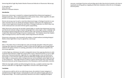
Summary of Receiver Toughening Options. Quantification of the selected, nominal receiver augmentations are summarized in FIGURE 1 for both full accuracy (State 5, centimeter-level accuracy in RTK) and for less accurate code tracking (State 3, meter-level accuracy). These results are shown with a logarithmic scale to accommodate the wide range of denial radii.
")
Figure 1. Effect of receiver augmentations on accuracy for both State 5 and State 3. (Image: Brad Parkinson)
The example shows that a 1-kW hostile jammer’s denial radius10can be reduced by a factor of about 100, using the conservative example augmentations of inertial and CRPAs. Because area is proportional to radius squared, the effective denial area of an augmented receiver would be 1/10,000th of the unaugmented receiver, using the example values.
Reverting to code-only (State 3) tracking, it enables operating through higher levels of jamming, albeit with less ranging precision. All these receiver augmentations and tracking techniques would also offer a significant defense against any attempt to spoof (deceive) the position measurement. Again, none of these techniques are new; we demonstrated the capabilities at the original GPS Joint Program Office in 1978, more than 40 years ago. Today, many competent manufacturers are offering toughened GPS receivers with combinations and variations of these techniques.
")
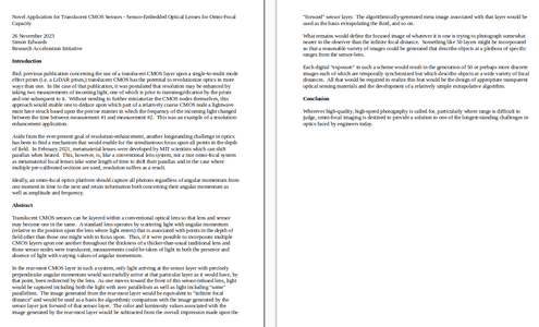
GPS jamming tests at White Sands have caused aircraft interference, which could be largely avoided with toughened receivers. Here, M-code is tested on Joint Light Tactical Vehicle platforms in 2020. (Photo: Joe Bullinger/U.S. Navy)
Threats of both jamming and spoofing seem to have accelerated. Devices to perform these illegal acts are freely advertised on the internet. In fact, we read of incidents both in the United States and abroad.11 Near White Sands Missile Range in New Mexico, there have been GPS air traffic control outages due to authorized military operational jamming exercises. Such interruptions could be largely avoided if more robust (toughened) GPS receivers, with the enhanced jam resistance techniques outlined here, were in use.
News reports also highlight the spoofing issue. Hardening against this threat is also a task for toughening. A serious spoofing sequence usually starts with a strong jamming signal to cause the user’s receiver to break lock, followed by a strong false GNSS signal that causes false lock by the receiver. Using the false signal leads to a false position, of course. The first line of defense is to avoid the break-lock threat. Failing this, numerous self-check and authentication schemes can be used to avoid false positions.
A conclusion is that avoiding the break-lock jamming is a first line of defense against a spoofing attack. Of course, the toughening techniques to avoid this are the main subject of this paper. One well-known expert has stated that, for a well-designed receiver, a spoofing attack might deny the measurement of position, but should never cause false PNT. I will leave further discussion of spoofing to other authors.
Returning to disruptions of service in general, some have suggested many interference occurrences have gone unreported, because the typical user would not know where to make such a report. To remind the reader, the official reporting center is online at www.navcen.uscg.gov/?pageName=gpsUserInput.
In addition, the U.S. Federal Communications Commission (FCC) has repurposed a portion of the spectrum adjacent to the main GNSS L1 frequency (1575 MHz). The agency is converting the license holder’s original authorization to transmit a weak space-transmitted signal into a much stronger terrestrial system, potentially with thousands of transmitters. Extensive testing of civil GPS receivers by the U.S. Department of Transportation demonstrated that the planned repurposing will interfere with many existing receivers. Some observers call this disruption “legal jamming.”
Such a new spectrum use could have grave impacts on those existing receivers, notably aviation (especially helicopters and UAVs) and first providers. On the other hand, installing toughened replacement receivers would make the users virtually immune to this threat.
So, this begs the question: If the receiver toughening techniques are so effective, why are they not more prevalent?
Let’s examine the potential resistance to more extensive use of receiver augmentations.
Knowledge. This involves underestimating the threat to PNT and not understanding that toughening techniques are available. As mentioned above, threats to the fragile GNSS signals are growing.
There seems to be little interest in the U.S. government to monitor and suppress interference in the United States. Internationally, the reported incidents continue to increase.12 It is also reported that certain European aircraft manufacturers have installed advanced, deeply integrated inertial systems with civil GNSS receivers to defeat or “flywheel” through radio-frequency threats (particularly in the Middle East).
As this threat trend continues, GPS manufacturers and users must realize that many of these solutions will take time to authorize, implement and install. It appears that the media are not aware that not only are the toughening techniques outlined here feasible, but many manufacturers have product offerings that address these threats. Having off-the-shelf solutions will give the PNT user the opportunity to retrofit and defeat such threats.
Cost. The cost for a receiver to revert from State 5 to State 3 is zero, and all receivers that use Code 5 (for example, RTK) would naturally have this built in. Regarding use of other frequencies (such as L5) and modulations (L1C) rather than the original L1 C/A, there is some small cost associated, including the additional antenna for L5. Note that all modern cellphone chips, such as Qualcomm’s, have this capability — including integrated carrier-phase measurements — in a chip that is estimated to cost about $5. A potential barrier is that the L5 and L1C signals are not yet declared operational, but these newer GPS signals should be operational within about five years.
The costs of many inertial components (accelerometers and gyros) have plummeted in the last few decades with the proliferation of MEMS devices, particularly into cellphones and automobiles. Their power consumption has also decreased while their performance has steadily improved. Full IMUs are much more expensive, but are already installed on many commercial aircraft. Robust toughening with inertial sensors can be achieved, but requires deep integration and careful engineering.
Depending on their complexity, CRPA antennas can be a costly receiver augmentation. Very high-speed (330 MHz is available), 16-bit, A-to-D converters are at the heart of most of these phased-array devices. Some are priced at about $150 each. Applications with a high premium for PNT availability in the face of interference — such as commercial aircraft and cargo ships — should find them affordable. Aircraft manufacturers have resisted retrofitting existing aircraft with larger diameter CRPA antennas because of costs. For some of these applications, integration costs can be more than the costs of the receiver itself, particularly if not included in the original manufacture.
As the yearly sales of fully toughened receivers increase, the economies of scale should significantly reduce unit costs. Each application will make its own determination of affordability, based on risk.
Government restrictions. Civil use of CRPAs with four or more elements is restricted by ITAR. These are well-meaning restrictions on technologies that could be used against the United States by hostile military forces. Unfortunately, the phased-array antenna techniques are not only well understood and tested, but relatively inexpensive components are widely available on the open world market. In particular, the restriction on the number of CRPA elements for civil use should be completely removed. All potential enemies are well aware of the beam-steering method and have ready access to the parts to build them. Thus, the restriction is only harming civil users without affording any apparent improvement in general military posture.
")
Certified aviation receivers need approval for deep integration of inertial systems and multi-element CRPAs. (Photo: JasonDoiy/iStock/Getty Images Plus/Getty Images)
Gaining permission: FAA flight certifications. To be used in commercial aircraft operations, navigation equipment must be certified by the U.S. Federal Aviation Administration (FAA). Current, certified GPS aviation receivers have rudimentary toughening techniques, but gaining approval for deep integration of inertial systems and multi-element CRPAs must be completed. It is gratifying to hear that work is underway to do this.
Any civil solution for the United States must expand integrity monitoring beyond GPS to include all GNSS, and must be operationally included in the FAA’s integrity monitoring with WAAS.
In describing resistance to interference, I have introduced the idea of DRRR – Denial Radius Reduction Ratio. Also, I have used a 1-kW white-noise jammer as a standard threat for calculating the denial radius of various GPS receiver configurations. My recommendation is that equipment manufacturers specify their receiver offerings by stating their equipment’s denial radius against a “standardized” 1-kW EIRP white-noise jammer.
See: https://www.gpsworld.com/toughen-gps-to-resist-jamming-and-spoofing/
A common use of jammers in London is related to taxi and HGV drivers evading rules on maximum driving hours, dodging location limitations or trying to stop employers from tracking them. In other parts of the world, GPS jamming has been used for more sinister purposes. South Korea was subject to a major campaign of GPS jamming from North Korea in 2016, affecting ship and aircraft navigation. With the advent of 5G systems moving into the frequencies used by GPS, interference is likely to become more and more widespread due to frequency drift* and bleed over. **
Whatever the target of a GPS jammer, the devices do not discriminate, so there is usually additional collateral damage. Air Traffic Control (ATC), search and rescue operations, the electric grid and mobile phone services are all vulnerable to successful GPS jamming fallout.
The London Stock Exchange has been subject to repeated GPS outages, affecting the accurate time stamping of financial transactions.
In 2007, a navy exercise on loss of GPS communications in San Diego harbor meant that residents of the city were unable to withdraw cash from ATMs and doctors’ emergency pagers stopped working – it took 3 days to identify the US Navy’s ships as the cause.
As jamming activity from civilian users becomes more prevalent, we risk similar disruptions as well as more fatal incidents such as aircraft colliding over populated areas.
Spectrum monitoring enables GPS jammers to be detected and located by mobile direction finding systems utilizing a multiple antenna array. Analysis of frequency spectra to determine duration of interference and signal type can also be used as an indication of whether the interference is accidental, bleed over from military or 5G systems or deliberate jamming. Those involved in unintentional jamming can then be warned and malicious attackers can be prosecuted. This results in quick resolution of disruption and danger caused by GPS jamming and acts as a preventative deterrent.
RFeye receivers have exceptional noise performance allowing detection and location over larger areas. Automation features minimize human intervention and allow triggering of alarms on detection of jamming activity. Our GPS holdover module also ensures accurate timing synchronization between receivers even if jamming activity (or poor reception) means GPS signal is lost. High-performance receiver boards can also be integrated into 3rd party anti-jamming and anti-spoofing systems for critical applications requiring a proactive approach. Anti-jamming and anti-spoofing systems can distinguish true GPS signals from jammers and spoofers, enabling GPS location and timing services to continue even while under attack.
It is recommended that law enforcement implement a wider strategy of spectrum monitoring to combat the rise in GPS jamming activity. Any organisation highly dependent on GPS services, whether a stock exchange, Air Traffic Control or the 911 System is also advised to operate a dedicated counter-jamming system to ensure continuous protection of this critical infrastructure.
GPS spoofing is a more insidious form of attack, which involves deliberately mimicking the form of transmissions from GPS satellites, tricking the receiver into believing that it has been sent information as expected. GPS spoofing in its simplest form (sometimes called denial-of-service spoofing) involves location information being sent to the GPS receiver which is clearly false (it might, for instance, tell a ship out at sea that it is currently located on land or that a police vehicle is in a lake or at sea).
It is immediately clear to the user that they are being spoofed, but it nonetheless stops them using their GPS system for its intended purpose. In these circumstances, spoofing basically functions as a more targeted form of jamming, that only affects GPS systems, rather than flooding the entire RF environment with noise.
An even more subtle and complex form of GPS spoofing, deception spoofing, involves hijacking GPS systems by initially sending them correct location information (so the spoofing is not immediately obvious), and then very slowly changing the information being sent over time so that, for instance, it can drag vessels off course into hostile waters, or disable a vessel on a sand bank.
GPS satellites send out a pseudo-random code, and receivers on the ground can tell from this code what time the signal was sent from each satellite. This allows them to determine how long the signal takes to reach them, and therefore how far from each satellite they are.
The obvious way to determine if spoofing is taking place is to work out where the received signals are coming from. If it turns out to be sent from near to the receiver, rather than high in the atmosphere, we can be fairly certain the receiver is being spoofed. This is where specialty systems come in. Using a network of at least four RFeye Nodes, a time difference of arrival (TDOA) calculation can be performed to find out where it originated. Not only does this allow the spoofing to be detected, but knowing the location of the spoofers can allow measures to be taken to shut it down at source.
It might be helpful to examine the CFRS catalogue of GPS systems at: https://www.crfs.com/.
They offer a wide panoply of GPS systems and anti-jamming technologies.
Hartmann352
* Frequency drift: is an undesired change or variation in the frequency of an oscillator from its nominal value over time. Frequency drift can be caused by numerous factors, including electronic component aging, changes in temperature that alter the piezoelectric effect in the crystal oscillator, problems with voltage regulators which control the bias voltage to the oscillator, and other causes such as mechanical vibration & electromagnetic interference (EMI). The EMI can introduce noise or disturbances that influence the frequency stability. Frequency drift is typically measured in Hz/s (frequency/seconds). The absence (or very low level) of frequency drift can be regarded as frequency stability.
Frequency drift may not necessarily be linear and can occur in either direction (i.e., increasing or decreasing in frequency). It usually occurs in devices that generate frequency signals or process them like oscillators, clocks, transmitters, receivers, and repeaters.
Frequency drift can affect a system's performance. For example, in the case of a transmitter, the frequency drift can lead to a radio station drifting into an adjacent channel, thereby causing unauthorized interference and violating regulations. This is why Frequency allocation regulations specify allowed tolerances for oscillators used in certified products/devices. Frequency drift can also cause errors in data transmission, due to loss of synchronization issues, or reduced signal quality.
See: https://www.everythingrf.com/community/what-is-frequency-drift
** Frequency bleed over: means a strong signal on an adjacent frequency is "bleeding over" or leaking into the channel you're listening to and has nothing to do with overload, intermodulation or intermediate frequency (IF) images but rather it is the insufficient receiver selectivity to reject it. In this case an external filter of any sort will not help, the frequencies are too close together to reject the unwanted one without severely attenuating the wanted one.
Sometimes a few tricks may help like setting the channel to narrow band (NFM) which narrows down the channel width (increased selectivity). Another is programming the frequency slightly offset up or down away from the offending signal but first you must determine whether the offending one is above or below the wanted one.
One may choose to:
- Reduce the total signal level coming in to the scanner. But that reduces the desired signal as well as the undesired signal.
- Use a better quality receiver. However, even the best quality receiver may not be good enough.
- Add a CT/DC tone to the desired channel's settings. If they do not use a tone, you are out of luck. If they do, this will keep the scanner from stopping when there is only bleed-over, but will not stop the bleed-over from interfering when both signals are present.
- If the source of the bleed-over is from a specific direction, you might be able to physically block signals coming from that direction to your antenna. This gets a little tricky, and require that the offending signal is not also bouncing off an object and coming in to your antenna from a different direction.
- If the desired signal is from a specific direction, and the undesired signal from a different direction, you might be able to use a directional antenna to "focus" in on the desired signal.
See: https://forums.radioreference.com/threads/ways-to-stop-bleedover.173247/
Having gone over the causes, except for electromagnetic pulses, look at the various ways that the GPS may be hardened.
The received GPS signal is 1/10th of 1 millionth of 1 billionth of a Watt. It can be susceptible to jamming and spoofing.
In response, the U.S. government has sponsored major studies and some competitive tests of techniques to augment or possibly replace GPS. I applaud such queries, but also would strongly advocate more balance in efforts to increase the robustness of positioning, navigation and timing (PNT).
Specifically, I argue for increased emphasis on well-known techniques that can greatly toughen GNSS receivers to both jamming and spoofing. Some of these techniques are deliberately denied to civil users by US government policy.
The PNT Advisory Board (PNTAB) is a panel of national experts who report to the PNT ExCom. The ExCom is comprised of the deputy heads of the nine U.S. government departments with the largest stakes in PNT. The PNTAB has a starkly simple and well-stated goal:
To meet its overarching goal, the PNTAB has developed a three-legged strategic framework, known as “PTA”: “We must protect, toughen and augment GPS to ensure that it continues to provide economic and societal benefits to the nation.”
Most current U.S. government efforts have been focused on the third of the PNTAB strategic legs: augmenting the GPS system. These system augmentations include: modernized Loran (eLoran), fiber-optic distribution of time, and ranging to low-Earth-orbit (LEO) satellites (particularly the swarms of communications satellites). In general, these system augmentations offer no hope of being equivalent to GPS in terms of availability and accuracy.
However, augmentations have the advantage of either being less vulnerable to interference, or highly proliferated in case of satellite outages. As supplements, or in an emergency, they can perform a very valuable role, but with nowhere near the equivalent performance of normally operating GNSS, which can routinely provide worldwide, 24/7 precisions better than decimeters in the dynamic real-time kinematic (RTK) mode. In the United States, GPS also offers continuous, real-time integrity assessments courtesy of the FAA1. Europe has a similar, compatible integrity system called EGNOS, and there are other regional system augmentations.
In summary, the current PNTAB assessment regarding these substitutes is:
“No current or foreseeable alternative to GNSS (primarily GPS) can deliver the equivalent accuracy (static down to millimeters) and worldwide, with 24/7 availability.”
Toughening, the second leg of our assurance strategy, includes all aspects of GPS enterprise vulnerability — satellites, ground control and user equipment. For this article, I am focused on toughening the user equipment. I would argue that we have largely under-emphasized, or been prohibited by national policy from using, well-known and widely available user equipment toughening technology.
The main vulnerabilities of GPS receivers are jamming and spoofing of the received signals. Familiar anti-jam (A/J) methods can substantially overcome the inherent weakness of GPS signals to defeat deliberate jamming and spoofing. As I outline here, such measures can reduce a jammer’s effective radius by a factor of more than 100 and reduce the effective jammer area by a factor of 10,000 compared to the unprotected receiver.2
Thus, these methods are also deterrents, because they can render ineffective such hostile (or possibly inadvertent) acts. Further, the technology that provides this significant toughening is available now or will be within a few years, rather than the many years required by some alternative, system-level augmentations.
Toughening techniques (A/J improvements) are traditionally calibrated as the improvement in the amount of jamming that can be tolerated, measured by the jamming-to-signal power ratio (J/S) expressed as decibels (dB). However, for this discussion, I will also use a different, more intuitive, measure. This metric is the Denial Radius Reduction Ratio (DRRR):
DRRR = (radius of jammer denial after J/S measure applied)/(jammer radius without improvements)
For example, a 15-dB improvement in J/S would lead to a DRRR of 0.178.3 In other words, the 15-dB improvement has reduced the denial radius to about 18% of the line-of-sight radius that would be denied to an untoughened receiver. Note that the simultaneous use of techniques is generally multiplicative. For example, simultaneously applying technique #1 with a DRRR1 of 0.5 and technique #2 with a DRRR2 of 0.3, would result in a DRRR1&2 of 0.3 *0.5, or an overall DRRR of 0.15. This is the advantage of using this metric to describe the A/J improvements. 4
For our basis for comparison, we will consider the L1 C/A signal in full accuracy (State 5) tracking mode and a 1-kW noise jammer.5,6 For this situation, the line-of-sight jammer could deny GPS to a radius of about 560 kilometers. A discussion of the lower accuracy State 3 tracking is included below.
It is useful to consider toughening techniques in four major categories.
Toughening Category 1: Signal Processing. With L1 C/A, GPS receivers can improve jamming resistance, albeit with loss of ranging (tracking) accuracy, by using code tracking mode – State 3. This reduces a line-of-sight jammer’s denial radius (DRRR) to about 0.29 (a 10.7 dB improvement).
Toughening Category 2: Inertial Components and Very Stable User Clocks. This includes miniature micro-electromechanical (MEMS) components up to high-grade inertial measurement units (IMUs) and quartz to chip-scale atomic clocks (CSACs). These techniques enable narrower tracking filters and longer averaging, as well as allowing navigation through regions when GPS is denied. The range of DRRRs is 0.40 down to 0.10. We will use a nominal value of 0.18 (a 15-dB improvement).
Toughening Category 3: CRPAs. Controlled reception pattern antennas (CRPAS) are digital, multi-element, phase-steered antennas. They represent well-understood and available technology; they have been used in large surface-search radar systems for many decades.7 They can be used in null-steering or beam-steering modes.8 The number of antenna elements could range up to dozens. Potentially, they could produce DRRRs down to .01 — that is, a 99% reduction of jammer radius to 1% of the unprotected GPS receiver value.
Unfortunately, the U.S. government does not allow more than three-element CRPAs to be manufactured or sold for civil use. 9This is due to some very old International Traffic in Arms Regulations (ITAR). For our nominal example, we will assume the restriction has been relaxed and use a CRPA of about 20 elements, which should produce a DRRR of 0.06 (a 25-dB improvement).
Toughening Category 4: Signal Alternatives. This category includes alternative modulations at 1575 MHz (L1C, Galileo or other GNSS) and alternative frequencies (L5, L2, Galileo). Note that the modern signals generally offer significantly improved signal-processing toughening as well as increased power.
Using L1C in State 3 compared to L1 C/A in State 5 would yield a DRRR of 0.10. (a 20.3-dB improvement). The L1C international signal should be operational on GPS by mid-decade. The L5 signal, at 1176 MHz, is clearly the most capable of the civil GPS signals in terms of jam resistance. L5 also should be declared operational by mid-decade. As the use of LEO communication satellites matures, their use may also fit this category.
Summary of Receiver Toughening Options. Quantification of the selected, nominal receiver augmentations are summarized in FIGURE 1 for both full accuracy (State 5, centimeter-level accuracy in RTK) and for less accurate code tracking (State 3, meter-level accuracy). These results are shown with a logarithmic scale to accommodate the wide range of denial radii.
Figure 1. Effect of receiver augmentations on accuracy for both State 5 and State 3. (Image: Brad Parkinson)
The example shows that a 1-kW hostile jammer’s denial radius10can be reduced by a factor of about 100, using the conservative example augmentations of inertial and CRPAs. Because area is proportional to radius squared, the effective denial area of an augmented receiver would be 1/10,000th of the unaugmented receiver, using the example values.
Reverting to code-only (State 3) tracking, it enables operating through higher levels of jamming, albeit with less ranging precision. All these receiver augmentations and tracking techniques would also offer a significant defense against any attempt to spoof (deceive) the position measurement. Again, none of these techniques are new; we demonstrated the capabilities at the original GPS Joint Program Office in 1978, more than 40 years ago. Today, many competent manufacturers are offering toughened GPS receivers with combinations and variations of these techniques.
GPS jamming tests at White Sands have caused aircraft interference, which could be largely avoided with toughened receivers. Here, M-code is tested on Joint Light Tactical Vehicle platforms in 2020. (Photo: Joe Bullinger/U.S. Navy)
Threats of both jamming and spoofing seem to have accelerated. Devices to perform these illegal acts are freely advertised on the internet. In fact, we read of incidents both in the United States and abroad.11 Near White Sands Missile Range in New Mexico, there have been GPS air traffic control outages due to authorized military operational jamming exercises. Such interruptions could be largely avoided if more robust (toughened) GPS receivers, with the enhanced jam resistance techniques outlined here, were in use.
News reports also highlight the spoofing issue. Hardening against this threat is also a task for toughening. A serious spoofing sequence usually starts with a strong jamming signal to cause the user’s receiver to break lock, followed by a strong false GNSS signal that causes false lock by the receiver. Using the false signal leads to a false position, of course. The first line of defense is to avoid the break-lock threat. Failing this, numerous self-check and authentication schemes can be used to avoid false positions.
A conclusion is that avoiding the break-lock jamming is a first line of defense against a spoofing attack. Of course, the toughening techniques to avoid this are the main subject of this paper. One well-known expert has stated that, for a well-designed receiver, a spoofing attack might deny the measurement of position, but should never cause false PNT. I will leave further discussion of spoofing to other authors.
Returning to disruptions of service in general, some have suggested many interference occurrences have gone unreported, because the typical user would not know where to make such a report. To remind the reader, the official reporting center is online at www.navcen.uscg.gov/?pageName=gpsUserInput.
In addition, the U.S. Federal Communications Commission (FCC) has repurposed a portion of the spectrum adjacent to the main GNSS L1 frequency (1575 MHz). The agency is converting the license holder’s original authorization to transmit a weak space-transmitted signal into a much stronger terrestrial system, potentially with thousands of transmitters. Extensive testing of civil GPS receivers by the U.S. Department of Transportation demonstrated that the planned repurposing will interfere with many existing receivers. Some observers call this disruption “legal jamming.”
Such a new spectrum use could have grave impacts on those existing receivers, notably aviation (especially helicopters and UAVs) and first providers. On the other hand, installing toughened replacement receivers would make the users virtually immune to this threat.
So, this begs the question: If the receiver toughening techniques are so effective, why are they not more prevalent?
Let’s examine the potential resistance to more extensive use of receiver augmentations.
Knowledge. This involves underestimating the threat to PNT and not understanding that toughening techniques are available. As mentioned above, threats to the fragile GNSS signals are growing.
There seems to be little interest in the U.S. government to monitor and suppress interference in the United States. Internationally, the reported incidents continue to increase.12 It is also reported that certain European aircraft manufacturers have installed advanced, deeply integrated inertial systems with civil GNSS receivers to defeat or “flywheel” through radio-frequency threats (particularly in the Middle East).
As this threat trend continues, GPS manufacturers and users must realize that many of these solutions will take time to authorize, implement and install. It appears that the media are not aware that not only are the toughening techniques outlined here feasible, but many manufacturers have product offerings that address these threats. Having off-the-shelf solutions will give the PNT user the opportunity to retrofit and defeat such threats.
Cost. The cost for a receiver to revert from State 5 to State 3 is zero, and all receivers that use Code 5 (for example, RTK) would naturally have this built in. Regarding use of other frequencies (such as L5) and modulations (L1C) rather than the original L1 C/A, there is some small cost associated, including the additional antenna for L5. Note that all modern cellphone chips, such as Qualcomm’s, have this capability — including integrated carrier-phase measurements — in a chip that is estimated to cost about $5. A potential barrier is that the L5 and L1C signals are not yet declared operational, but these newer GPS signals should be operational within about five years.
The costs of many inertial components (accelerometers and gyros) have plummeted in the last few decades with the proliferation of MEMS devices, particularly into cellphones and automobiles. Their power consumption has also decreased while their performance has steadily improved. Full IMUs are much more expensive, but are already installed on many commercial aircraft. Robust toughening with inertial sensors can be achieved, but requires deep integration and careful engineering.
Depending on their complexity, CRPA antennas can be a costly receiver augmentation. Very high-speed (330 MHz is available), 16-bit, A-to-D converters are at the heart of most of these phased-array devices. Some are priced at about $150 each. Applications with a high premium for PNT availability in the face of interference — such as commercial aircraft and cargo ships — should find them affordable. Aircraft manufacturers have resisted retrofitting existing aircraft with larger diameter CRPA antennas because of costs. For some of these applications, integration costs can be more than the costs of the receiver itself, particularly if not included in the original manufacture.
As the yearly sales of fully toughened receivers increase, the economies of scale should significantly reduce unit costs. Each application will make its own determination of affordability, based on risk.
Government restrictions. Civil use of CRPAs with four or more elements is restricted by ITAR. These are well-meaning restrictions on technologies that could be used against the United States by hostile military forces. Unfortunately, the phased-array antenna techniques are not only well understood and tested, but relatively inexpensive components are widely available on the open world market. In particular, the restriction on the number of CRPA elements for civil use should be completely removed. All potential enemies are well aware of the beam-steering method and have ready access to the parts to build them. Thus, the restriction is only harming civil users without affording any apparent improvement in general military posture.
Certified aviation receivers need approval for deep integration of inertial systems and multi-element CRPAs. (Photo: JasonDoiy/iStock/Getty Images Plus/Getty Images)
Gaining permission: FAA flight certifications. To be used in commercial aircraft operations, navigation equipment must be certified by the U.S. Federal Aviation Administration (FAA). Current, certified GPS aviation receivers have rudimentary toughening techniques, but gaining approval for deep integration of inertial systems and multi-element CRPAs must be completed. It is gratifying to hear that work is underway to do this.
Any civil solution for the United States must expand integrity monitoring beyond GPS to include all GNSS, and must be operationally included in the FAA’s integrity monitoring with WAAS.
In describing resistance to interference, I have introduced the idea of DRRR – Denial Radius Reduction Ratio. Also, I have used a 1-kW white-noise jammer as a standard threat for calculating the denial radius of various GPS receiver configurations. My recommendation is that equipment manufacturers specify their receiver offerings by stating their equipment’s denial radius against a “standardized” 1-kW EIRP white-noise jammer.
Summary
Media reports of interference to GPS may be accurate, but they generally do not recognize that available toughening techniques can largely defeat those interference threats. While exploring systems-level replacements or augmentations (such as LEO ranging or Loran) is worthwhile, GPS (or GNSS) still offers the greatest capability in combined terms of accuracy, integrity and coverage.See: https://www.gpsworld.com/toughen-gps-to-resist-jamming-and-spoofing/
In response to that gpsworld article, I'd have to say that Brad isn't up to date on what's been going on in the past seven or so years. It is a shame that even Ph.D.s are so aloof. GPS 3.0 cannot be jammed using the methods mentioned there, it's based upon filtering signals according to both helicity and angular momentum. In theory, if you can keep your GPS system working reliably (i.e. all of your drone and other assets are in known physical locations at all times) a similar multi-layered helicity/angular momentum filtering system can be employed for air-to-ground and air-to-air communications. It's useful not only for preventing the jamming of GPS, but useful for preventing jamming generally where the relative position and directional orientation of transmitters and receivers are known with high confidence.
These sorts of methods can be augmented by conveying data concerning the timing of authentic messages, as I laid out in September, just prior to sending a message. If the expected time of receipt of an authentic message can be made known, noise can be algorithmically reduced with greater efficacy.
If you look at some of the incidents in which civilian cargo vessels collided with U.S. warships, thus disabling them, their GPS systems were being tampered with. No further such incidents have happened since the newer constellation went into place. The Navy has maintained since 2017 that those incidents were the result of human error.
Also, if this subject interests you, you may be interested in the early 2023 Chinese balloon incident(s.) In those incidents, balloons were deployed from orbit and were decelerated via the inflation of the balloons upon re-entry; a capability the U.S. lacks. The U.S. lied and claimed it was shooting them down with F-22s when it, in reality, captured the balloons using the same mechanism used for years to pluck film capsules out of the sky after re-entry with C-130s. Where it gets even more interesting is what the Chinese were investigating in Northern Alaska. The U.S. had emplaced neutrino detectors in the Arctic meant to be used in conjunction with tachyon emitters in orbit. That one they called the LOFTID system which, ironically, they claimed had to do with testing atmospheric re-entry balloons.
The recurring theme is that the U.S. is 30 steps behind, in any case. Want to work at DARPA? Have good ideas? Too bad, we don't hire anyone without Ph.D.s, that's the motto. You could literally have an idea that could save the world and they will plug their ears and hum loudly to avoid hearing it.
285 - 8 December 2023 - Mechanism for Isolation of Directionally Purified Signals in a Single, Positionally Unstable Receiver via Novel Signals Analysis Technique Cross-Referencing Measured Rate of Change of Amplitude of Current and Measured Rate of Change of Magnetic Flux Associated with a Fractional Waveform
Updated 9 December 2023 to correct an editorial oversight in the sub-title regarding the mechanism of frequency inference from a partial wave sample
Updated 9 December 2023 to correct an editorial oversight in the sub-title regarding the mechanism of frequency inference from a partial wave sample
Attachments


Last edited:
Similar threads
- Replies
- 2
- Views
- 663
- Replies
- 4
- Views
- 1K
- Replies
- 3
- Views
- 6K
TRENDING THREADS
-
 George Washington's stash of centuries-old cherries found hidden under Mount Vernon floor
- Started by admin
- Replies: 14
-
 What is a living individual and is it naturally universally mobile?
- Started by tonylang
- Replies: 138
-

Live Science is part of Future plc, an international media group and leading digital publisher. Visit our corporate site.
© Future Publishing Limited Quay House, The Ambury, Bath BA1 1UA. All rights reserved. England and Wales company registration number 2008885.